I2C EEPROM Programming using Aardvark Adapter and Control Center Batch Mode
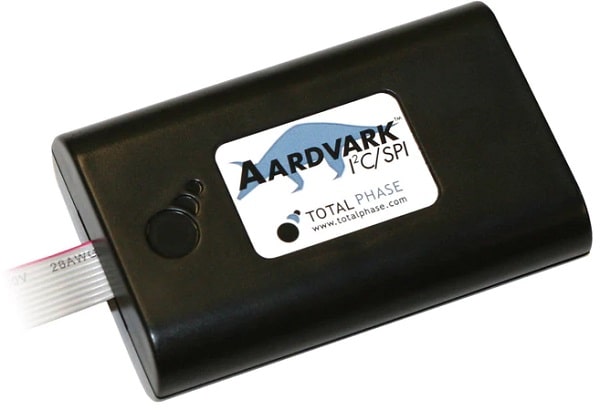
Programming and reading I2C memory devices is a common use case for the Aardvark I2C/SPI Host Adapter. There are several ways to do this with the Aardvark adapter, including using Control Center, Flash Center, or the Aardvark API. This article focuses on how to take the information in an EEPROM datasheet and execute the commands in Control Center Batch mode. Although the following describes the AT24C02 I2C EEPROM found on the I2C/SPI Activity Board, similar steps can be used for other devices. The goal of this article is to demonstrate how to write several bytes to a specific address and then read back those bytes.
The Aardvark adapter is the I2C master and the Atmel I2C EEPROM AT24C02 on the I2C/SPI activity board is the I2C slave.
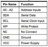
AT24C02 Detailed
The AT24C02 SCL (Serial Clock Input) and SDA (Serial Data) signals are connected to the Aardvark adapter SCL and SDA signals accordingly. The AT24C02 A0 - A2 (Address Input), WP (Write Protect) and GND (Ground) signals are connected to ground. The AT24C02 VCC (Power Supply) signal is connected to 3.3V.
The AT24C02 I2C EEPROM on the activity board has a hardware configurable I2C target address. The default I2C target address is 1010000b, which is 0x50. This article uses the default I2C target address 0x50. For additional information take a look at knowledge base article 7-bit, 8-bit, and 10-bit I2C Slave Addressing.
The AT24C02 on the I2C/SPI activity board receives the I2C pull-ups and power from the Aardvark adapter. In order to supply the I2C pull-ups and target power to the Activity board, the Aardvark adapter and Control Center are configured with the batch command "configure" to I2C/SPI mode (i2c="1" spi="1" gpio="0"), I2C pull-ups enabled (pullups="1"), and target power enabled (tpower="1"). For additional information take a look at the I2C/SPI activity board user's manual.
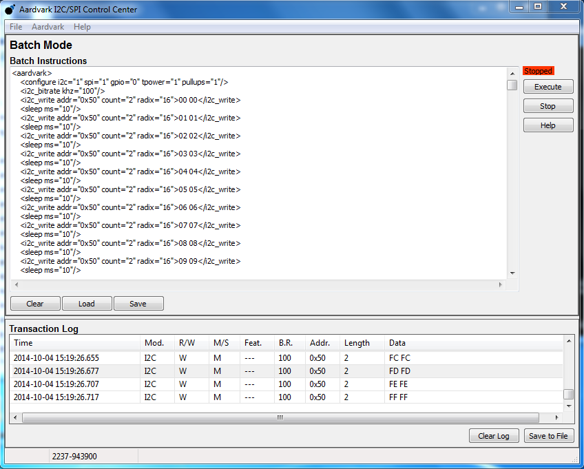
The AT24C02 write operation used here is Page Write. The Page Write operation to the AT24C02 requires 7 bit device address, one byte memory address, and two or more bytes of memory data. Performing a memory write operation with the Aardvark adapter requires a single command from the adapter and Control Center. In this case, Control Center batch mode example "i2c-eeprom-write" is used in order to perform 256 "i2c_write" commands of data 0x00 - 0xFF to memory addresses 0x00 to 0xFF with I2C device address 0x50. For example, take a look at the first and last i2c_write commands.
<i2c_write addr="0x50" count="2" radix="16">00 00</i2c_write>
<i2c_write addr="0x50" count="2" radix="16">FF FF</i2c_write>
The first command includes the device address (addr="0x50"), number of data bytes (count="2"), data format (radix="16"), memory address (0x00), and memory data (0x00). While the last "i2c_write" command includes the I2C device address (addr="0x50"), number of data bytes (count="2"), data format (radix="16"), memory address (0xFF), and memory data (0xFF).

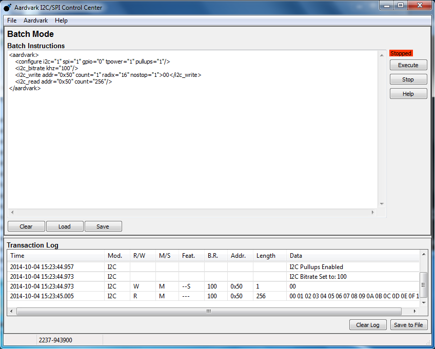
The AT240C read operation used here is the Sequential Read. The AT240C Sequential Read operation first performs I2C write with 7 bit device address, one byte memory address and no stop. Then the AT240C Sequential Read operation performs I2C read with 7 bit device address, two or more bytes of memory data, and stop. Performing a memory read operation with the Aardvark adapter requires two commands from the adapter and Control Center batch mode. In this case, Control Center batch mode example "i2c-eeprom-read" is used in order to perform read of 256 bytes from address 00 with I2C device address 0x50. In this article the memory read operation includes the following two Aardvark adapter and Control Center batch mode commands:
<i2c_write addr="0x50" count="1" radix="16" nostop="1">00</i2c_write>
<i2c_read addr="0x50" count="256"/>
- The first command is "i2c_write" including the I2C device address (addr="0x50"), number of data bytes (count="1"), data format (radix="16"), memory address (0x00), with no stop (nostop="1"). This write command is for configuring the internal data word address counter to a specific address (0x00).
- The second command is "i2c_read" including the I2C device address (addr="0x50") and the number of the data bytes (count="256"). This read command is to read the data starting from address 0x00.
For additional information take a look at the AT24C02 datasheet.

Writing and Reading Guidelines
- Download and run the latest version of the Total Phase USB Drivers Installer.
- Download and unzip the latest version of Control Center.
- Connect the Aardvark adapter to the PC via the USB connector.
- Connect the Aardvark adapter to the I2C/SPI activity board via the I2C/SPI connector.
- Launch Control Center.
- Connect to the Aardvark adapter.
- Click Configure Aardvark Adapter.
- Select the Aardvark Adapter.
- Click OK to connect to the adapter.
- Click Aardvark, and choose Batch Mode.
- Write to the memory
- Click Load, and choose i2c-eeprom-write.
- Click Open, and Execute.
9. Read from the memory (?)
Click Load, and choose i2c-eeprom-read.
Click Open, and Execute.
