Improved TDR measurements with the SIGLENT SNA5000A vector network analyser
Introduction
Time Domain Reflectometry (TDR) is an important method for measuring cable and link quality in high-speed transmissions. Measurements that generally fall into this category include characteristics such as distance to interference, as TDR can easily visualise impedance changes over distance. Some of the basic analysis modes can be implemented on cable analysers and simple spectrum analysers, but advanced TDR measurements allow much more subtle and elusive transmission quality issues to be assessed. When TDR capabilities are integrated into a powerful multi-channel vector network analyser, advanced visualisation and analysis are possible. One important method is the use of simulated eye diagrams on high-speed communication channels. These eye diagrams can be implemented on a range of device topologies with de-embedding using a 4-port network analyser while providing important data visualisations, including mask testing and injected jitter. This application note discusses the advanced TDR implementation and capabilities of the Siglent SNA5000A vector network analyser while comparing the quality of two standard USB cables.
Differential measurements and DUT topology
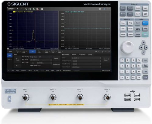
As with many VNA measurements, configuration and calibration are two of the most important steps in capturing quality data to inform design and improvements. Siglent's SNA5000A Vector Network Analyser includes a setup wizard that simplifies device configuration and calibration to unbundle cables and connections.
TDR mode is accessed via the MATH menu. After switching on, call up the setup wizard to get started. The first set-up step is to decide on the test item topology
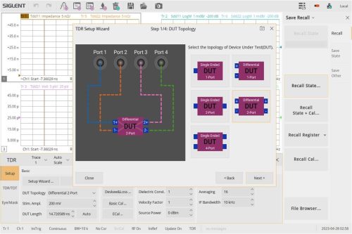
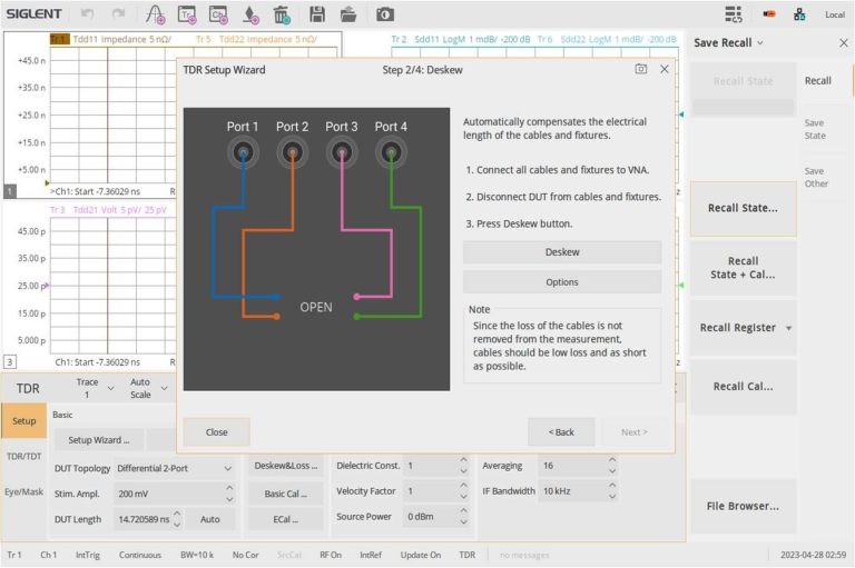
Complete differential measurements are possible with a 4-port VNA. This is important for high power signals and systems that routinely use differential signal transmission for high speed communication. Here we will use a 2-port differential topology to test our USB cables. We have two differential SMA-to-USB-A ports that we will connect to the VNA using N-to-SMA cables and adapters. The next steps in the setup wizard help to calibrate and equalise these cables and connectors for our selected topology. The figure shows the first opened window of the calibration wizard. This is followed by some through connections and optional load connections to calibrate the setup for your device. Additional mechanical calibrations or Ecal can also be performed via the TRD setup interface.
Use the Auto Scale function to scale all traces and we can visualise any of the parameters of interest. The SNA5000A can create up to 256 traces at once. Much of the analysis can be done in the view shown in the figure. The traces in the time domain fully characterise the device under test. We can take a quick look to ensure that our device is connected correctly and is measuring within the specified parameters. Now we can switch to the eye diagram view for an extended characterisation of this connection.
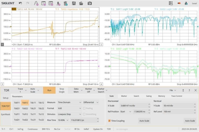
Once the setup wizard is complete, you can configure the measurement curves on the display for the desired measurements. In this topology, you can choose from the following options:
| Tdd11 | Tdd12 | Tdc11 | Tdc12 |
| Tdd21 | Tdd22 | Tdc21 | Tdc22 |
| Tcd11 | Tcd12 | Tcc11 | Tcc12 |
| Tcd21 | Tcd22 | Tcc21 | Tcc22 |
These measurements are time domain parameters, where c and d (e.g. in: Tcd12) indicate whether the output and input connections are configured for differential or common measurements. The 1 and 2 indicate the number of the output and input port respectively. Conventional scattering parameters, such as Sdd12, can also be selected by changing the time range option. Other measurement formats, including Smith charts, can also be displayed in S-parameter mode. For our cable test, we will use Tdd12 to measure the differential transmission quality.
Related articles
RF noise figure measurements Spectrum analyzer SVA1032X
The noise figure is crucial in microwave production and measurement

Synchronisation of multiple function generators
Multi-channel function generators are versatile and important in radar tests and for simulating current distortion

Test open socket communication with PuTTY
In test instrumentation, an open socket is a fixed address for remote commands on the Ethernet/LAN bus.

Resolver simulation with an arbitrary waveform generator
A resolver is an electromagnetic sensor that determines the angle and speed of shafts and axes


