


RF noise figure measurements with the SVA1032X spectrum analyser
Introduction
Noise figure is an important measurement parameter in the process of microwave product development and production, and its measurement is an important element of noise measurement. This manual describes in detail the use of a spectrum analyser to measure noise coefficients with the Siglent SVA 1032X (9kHZ - 3.2GHz), including the filter response of the spectrum analyser, the derivation of noise coefficients, the calculation of cascaded output noise, etc.
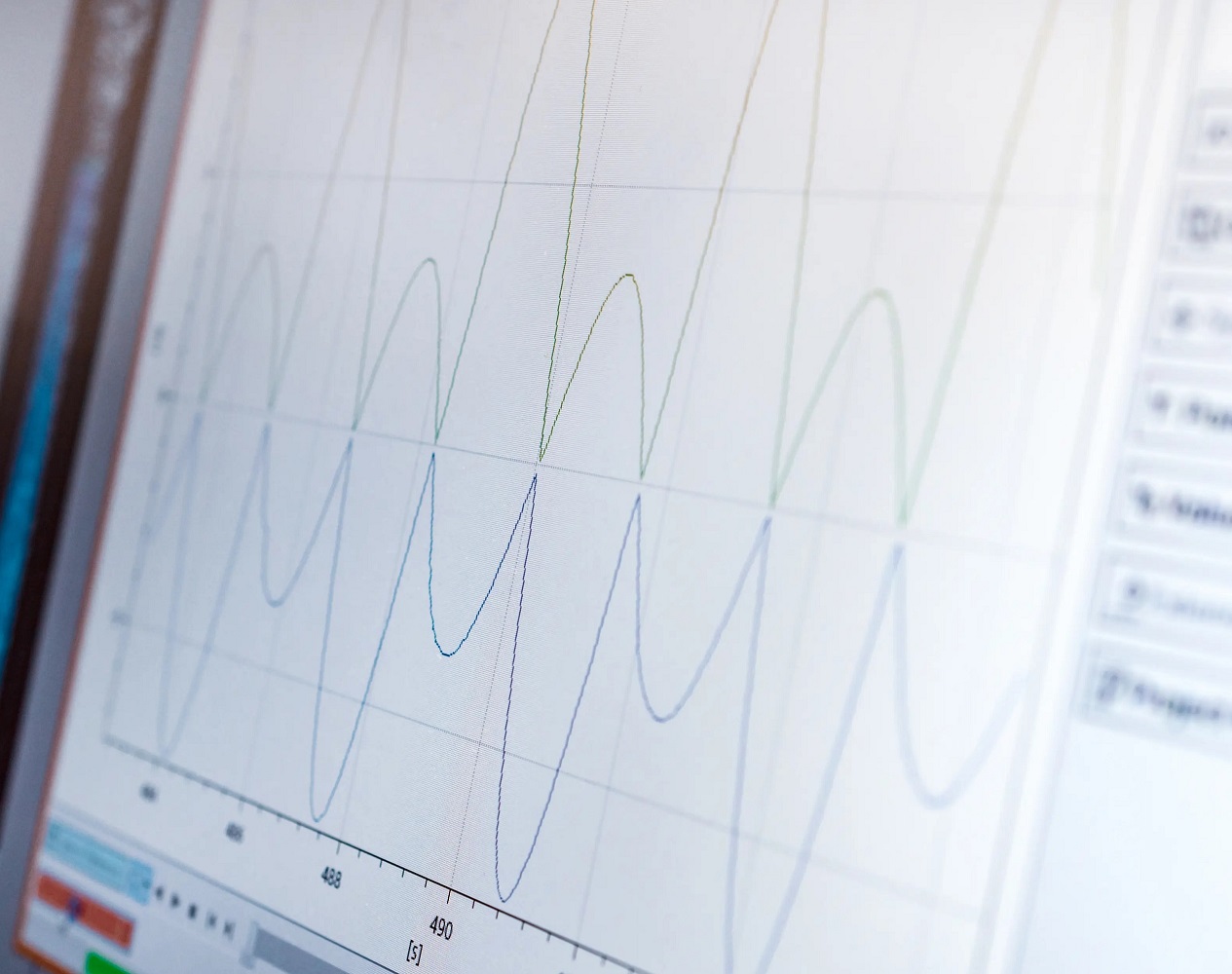
Spectral analyser filter response - RBW
The following procedure is used to measure the filter response or shape factor of the resolution bandwidth. Knowledge of the form factor is useful when measuring the noise figure. The procedure covers the measurement of the form factor of 100, 1kHz and 10kHZ RBW; however, it can also be used for other RBW and frequency settings.
Setup for SA and signal generator
1. Connect the 10 MHz clocks together, regardless of which is primary or secondary.
With Siglent devices, the external clock is automatically recognised and displayed during operation.
Ensure that the connectors are clean and correctly tightened.
2. Connect the RF output to the RF input of the spectrum analyser.
3. Setting for signal generator:
Pout=-10dBm
RF=CW @ 1GHz
ALC=automatic
4. Allow at least 30 minutes or more for the warm-up phase.
5. Set up spectrum analyser
6. Freq=1GHz
Frequency step size=10Hz (repeat the process with 100Hz and 1kHz
step size for the following RBW/VBW settings).
7. Span=0Hz
Trigger=Freewheel
Points=751, not adjustable
8. RBW/VBW=100Hz (repetition for 1kHz and 10kHz)
9. Attenuator=automatic
10. Preamplifier=off
11. Reference level=0 dBm
12. Scale/div=5 dB
13. Detector=Pos Peak
14. Sweep mode → Sweep rule → Accuracy
15. Sweep time=automatic
16. Mark=centre of the sweep
Measuring the form factor
- Switch the signal generator ON, set the RF output amplitude so that a value of -10 dBm is displayed on the spectrum analyser
- Increase/decrease the frequency of the spectrum analyser in 10Hz steps and record the values.
- Repeat this for other RBW/VBW settings and other frequency steps.
| Fc | Frequency | Delta (db) | RBW/VBW |
|---|---|---|---|
| 1 GHz | +/- 50Hz | 100Hz | |
| Fc - 50 Hz | -2,95 | ||
| Fc - 40 Hz | -1,87 | ||
| Fc - 30 Hz | -1,07 | ||
Fc - 20 Hz | -0,44 | ||
| Fc - 0 Hz | 0 | ||
| Fc + 20 Hz | -0,44 | ||
| Fc + 30 Hz | -1,08 | ||
| Fc + 40 Hz | -1,87 | ||
| Fc + 50 Hz | -2,94 |
| Fc | Frequency | Delta (db) | RBW/VBW |
|---|---|---|---|
| 1 GHz | +/- 500Hz | 1kHz | |
| Fc - 500 Hz | -3,0 | ||
| Fc - 400 Hz | -1,92 | ||
| Fc - 300 Hz | -1,08 | ||
Fc - 200 Hz | -0,47 | ||
| Fc - 0 Hz | 0 | ||
| Fc + 200 Hz | -0,49 | ||
| Fc + 300 Hz | -1,07 | ||
| Fc + 400 Hz | -1,91 | ||
| Fc + 500 Hz | -3,0 |
| Fc | Frequency | Delta (db) | RBW/VBW |
|---|---|---|---|
| 1 GHz | +/- 5kHz | 10kHz | |
| Fc - 5000 Hz | -3,02 | ||
| Fc - 4000 Hz | -1,94 | ||
| Fc - 3500 Hz | -1,51 | ||
Fc - 3000 Hz | -1,08 | ||
Fc - 2000 Hz | -0,48 | ||
| Fc - 0 Hz | 0 | ||
| Fc + 2000 Hz | -0,48 | ||
| Fc + 3000 Hz | -1,09 | ||
| Fc + 3500 Hz | -1,5 | ||
| Fc + 4000 Hz | -1,94 | ||
| Fc + 5000 Hz | -3,03 |
Related articles

RF noise figure measurements Spectrum analyzer SVA1032X
The noise figure is crucial in microwave production and measurement
Synchronisation of multiple function generators
Multi-channel function generators are versatile and important in radar tests and for simulating current distortion
Test open socket communication with PuTTY
In test instrumentation, an open socket is a fixed address for remote commands on the Ethernet/LAN bus.
DIY spectrum analyser input protection
SIGLENT spectrum analysers for broadcast signals, transmitter troubleshooting, interference and RF devices.