


Synchronisation of several function generators
1. Introduction
Multi-channel function generators are useful in many situations. In radar testing, for example, the generator must output several phase-coherent signals, whereby the phase must be independently adjustable for each signal. When testing harmonic distortion in 3-phase power lines, a 4-channel generator is required to simulate the different voltages and currents.
1.1 Problem definition
A stand-alone multi-channel generator can be very expensive.
1.2 Solution
Siglent offers the multi-device synchronisation function in the SDG2000X and SDG6000X generators. This enables synchronisation between several devices in order to output signals with adjustable, uniform phase ratios. This saves costs.
2. Setting up synchronisation
.

2.1 Cabling
Multi-device synchronisation requires the use of the Aux In/Out and 10 MHz In/Out interfaces on the rear of the device to implement synchronisation. Firstly, all Aux In/Out BNC connectors of the generators must be connected together. Then connect the 10 MHz output of the master device to the 10 MHz input of the slave device. Please note that the SDG6000X family has separate 10 MHz in/out outputs so that more than two devices can be synchronised. However, the 10 MHz input and output connections of the SDG2000X series share one connection. Therefore, only two devices can be synchronised together or they must be the last slave device in a connection with multiple devices.
In this note, the SDG2000X and SDG6000X series models are used as examples. The SDG6000X will be the master device.
- First connect the aux inputs and outputs of both devices with a BNC cable. See figure 1
- Then connect the 10 MHz output of the SDG6000X to the 10 MHz input/output of the SDG2000X as shown in Figure 2.


2.2 Parameter settings
Set the waveform parameters such as frequency and amplitude for all channels. For more information on this step, refer to the user manual.
Press Utility, go to page 2/3, select Phase Mode and then set both units as Phase Locked.
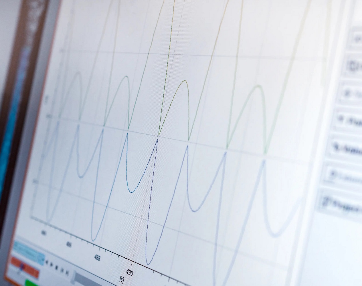
In this example, all 4 channels are set as 1 kHz, 4 Vpp square wave. The CH3 and CH4 signals seen on the SDS5000X oscilloscope are output from the slave generator; note that the phase drifts. open the Display/ Persist function to track them on the oscilloscope.
2.2.1 Setting the master device
1) Press Utility, go to page 3/3, and then press the soft button below the screen to select Multi-Device Sync. The menu opens the "Multi-Device Synchronisation" screen.


2) Press the soft button below the screen to switch this function on or off and select it as either master or slave. The "Multi-Devices Synchronisation" menu is displayed when it is switched on. If "Master" appears shaded in light grey, this means that the device is designated as the master device (see Figure 6). When this device is set as the master, its clock source is automatically set to internal and the 10 MHz output is activated.
2.2.2 Setting the slave device
1) Go to the Multi-Device Synchronisation menu. Select the device as a slave, slave is shaded blue, as shown in Figure 7. As the device is set as a slave device, its clock source is automatically set to external.


2) Switch on the status. The Slave Device Delay window is then displayed. Press to enter the delay value
2.2.3 Synchronising the devices
Press the "Syncs Devices" softkey in the multi-device synchronisation interface of the master device, as shown in Figure 1, to start synchronisation between the master and slave devices. Each time a setting is changed, e.g. the slave device delay, "Synchronise devices" must be pressed to activate the new settings.
3. Measurement with an oscilloscope

3.1 Measuring the slave device delay
1) Switch on the synchronisation on both devices and measure the offset between CH1 and CH3.
2) Enter the absolute mean value of Skew in Slave Device Delay. This eliminates the delay between the tracks observed with the oscilloscope.

3.2 Set phase relationship
Set CH1 phase to 0 degrees, CH2, CH3, CH4 phase to 180, 270 or 360 degrees.
Related block articles

RF noise figure measurements Spectrum analyzer SVA1032X
The noise figure is crucial in microwave production and measurement
Synchronisation of multiple function generators
Multi-channel function generators are versatile and important in radar tests and for simulating current distortion
Test open socket communication with PuTTY
In test instrumentation, an open socket is a fixed address for remote commands on the Ethernet/LAN bus.
DIY spectrum analyser input protection
SIGLENT spectrum analysers for broadcast signals, transmitter troubleshooting, interference and RF devices.