


Benefits of the System Power Management Interface (SPMI)
What is System Power Management Interface (SPMI)?
The complexity and performance requirements of cell phones and other portable electronic devices are increasing exponentially. As the demand for new high-performance, high-data-rate features increases, system-level power management becomes critical. Using advanced power management techniques to reduce power consumption and improve battery life is more important than ever.
The System Power Management Interface (SPMI) is a MIPI standard interface that connects the integrated power controller (PC) of a system-on-chip processor system (SoC) with one or more PMIC voltage regulation systems (Power Management Integrated Circuits). With SPMI, systems can dynamically adjust the supply and substrate biases of the voltage ranges within the SoC using a single SPMI bus.
To minimize the power consumption of digital processors in portable electronic devices, system and IC designers use advanced power management techniques.
Advanced hardware and software techniques are used to:
- Accurately monitor and control the level of processor performance required for a particular workload or application.
- Controlling Different Supply Voltages Based on Power Level The rapid deployment of such advanced power management techniques requires standardization of the interface. This SPMI specification (System Power Management Interface) deals with the standardization of the hardware interface.

How does SPMI work?
Within the SoC PC, the SPMI-related functions are referred to as “master”. Within PMIC, the SPMI-related functions are referred to as "slaves". Up to 4 masters and up to 16 slaves can be connected to the system. Multiple masters and slaves can reside on a single IC, multiple ICs, or any combination of both.
What are the advantages of SPMI?
SPMI offers a wide range of applications spread across industries that require better energy management. SPMI is used in smartphones, wearables, and other portable electronic devices. Smartphones and wearables use SPMI to control the performance of sensors. High-end smartphones already have several devices in their design and can require up to 20 signal lines. Any of these pins with independent power supply pins can cause problems. Similarly, most portable electronic devices would require a power management interface to optimize power consumption and reduce the number of pins. This requires for the standardized advanced power management interface.
What functions does SPMI offer?
SPMI is a two-wire serial advanced power management interface that connects the SoC processor system's integrated power regulator to one or more voltage regulation systems for integrated power management (PMIC) systems. The bidirectional two lines represent SDATA & SCLK. SDATA is a bidirectional data line and the SCLK is controlled by the master.
The SPMI protocol has the following features
- Bus arbitration is the process by which the bus is to be assigned to a master or a requesting slave among the devices that can simultaneously request a command sequence to be sent on the bus.
- Master Connect and Disconnect - A process by which a master can connect and disconnect from an initialized or uninitialized SPMI bus
- Communication initiated by the slave - A process for a Request Capable Slave (RCS) to initiate communication with the master or other slaves.
- There are two defined SPMI device classes:
- High-Speed (HS): 32 kHz to 26 MHz with a load of up to 50 pF
- Low speed (LS): 32 kHz to 15 MHz with a load of up to 50 pF
- ACK / NACK for robust communication.
SPMI Command Sequences
The episodes must belong to the following five years, which in turn are the:
- Bus Arbitration
- Transmission of the sequence start condition (SSC)
- Command of frames and one or more data frames)
- Transmission of ACK / NACK for command sequences.
- Transport of a bus park cycle
The last four events SSC, command / data frame, ACK / NACK & bus park cycle together form the command sequence. The SPMI specification names all command sequences on the interface under authority bits.
The sequence start condition must be a possible condition for the bus, which remains by a rising edge from a falling edge to a SDATA management, a SCLK to a logically connected level. The SSC is used by a slave or master to reference the start of a command sequence. SDATA is set by the bus master to a logical level of a period taken for an SCLK, then to the logical 0 level for an SCLK int period, the SCLK belongs to logical zero level.
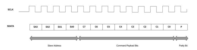
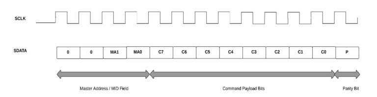
The command frame consists of 13 bits with a 4-bit address field, an 8-bit command field, and a separate parity bit.
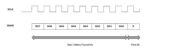
Data and address frames consist of 9 bits with 8 bits of data or address and a single parity bit.
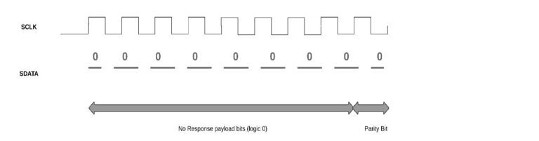
No response frame with a length of 9 bits if it is a data frame or 13 bits if it is a command frame.

SPMI Bus Arbitration
Bus arbitration is used to determine access to the bus for master / s or slave / s. The bus owner master oversees the arbitration and determines who has access to the bus. The various bus arbitration levels are displayed after the arbitration request in the order shown in the following figure.
Testing the SPMI-Protocol
The typical test setup for testing master or slave is as follows. The SPMI DUT can be an SPMI primary master, a secondary master, a requestable slave or a non-requestable slave. The software running on the host computer enables the user to configure the device either as a master or as a slave depending on the requirements in the DUT by selecting the appropriate selection.

SPMI Protocol Analyzer for testing SPMI designs
PGY-SPMI-EX-PD is the premier tool that designers and test engineers can use to test the SPMI designs for their specifications by configuring PGY-SPMI-EX-ED as master / slave and generating SPMI traffic with time variation and fault injection capability and decoding SPMI protocol packets.


Price on request