



LCR meter, impedance analyzer or VNA – which measuring device is suitable for which application?
LCR meter, impedance analyzer or VNA – which measuring device is suitable for which application?
Anyone characterizing components and materials quickly faces the question: Is a simple LCR meter sufficient, is an impedance analyzer necessary, or is a vector network analyzer (VNA) required? This article provides a practical overview – with a particular focus on the Techmize TH2851 impedance analyzers with test frequencies from 10 Hz to 130 MHz.
When is which measuring device useful?
LCR meters are particularly suitable for quick individual measurements of L, C and R at a few fixed frequencies – for example in goods receiving and simple production.
Impedance analyzers such as the Techmize TH2851 series cover a wide frequency range from 10 Hz to 130 MHz, capture multiple parameters in parallel and allow frequency sweeps, DC/AC bias as well as detailed analysis of resonances and material properties.
Vector network analyzers (VNAs) are classically used in RF applications when networks, lines and antennas with S-parameters are examined.
In many laboratories, quality control departments, and production facilities, an LCR meter is no longer sufficient when frequency response, parasitic effects, resonances, or material parameters need to be examined in detail. This is where an impedance analyzer demonstrates its strengths.
Key measurement parameters explained briefly
- Impedance (Z): Total resistance of a device under test to alternating current – including ohmic, inductive and capacitive components.
- ESR (Equivalent Series Resistance): Effective series resistance, which describes in particular the losses of capacitors.
- ESL (Equivalent Series Inductance): Effective series inductance, which leads to high-frequency resonances in real capacitors, for example.
- Q (quality factor): Ratio of stored energy to lossy energy; high Q values indicate low losses in a resonant component.
- D (Dissipation Factor): Loss factor, inverse of the quality factor; describes how lossy a component is at a given frequency.
- Resonance: Frequency at which inductive and capacitive components cancel each other out and impedance or current exhibits a characteristic maximum or minimum.
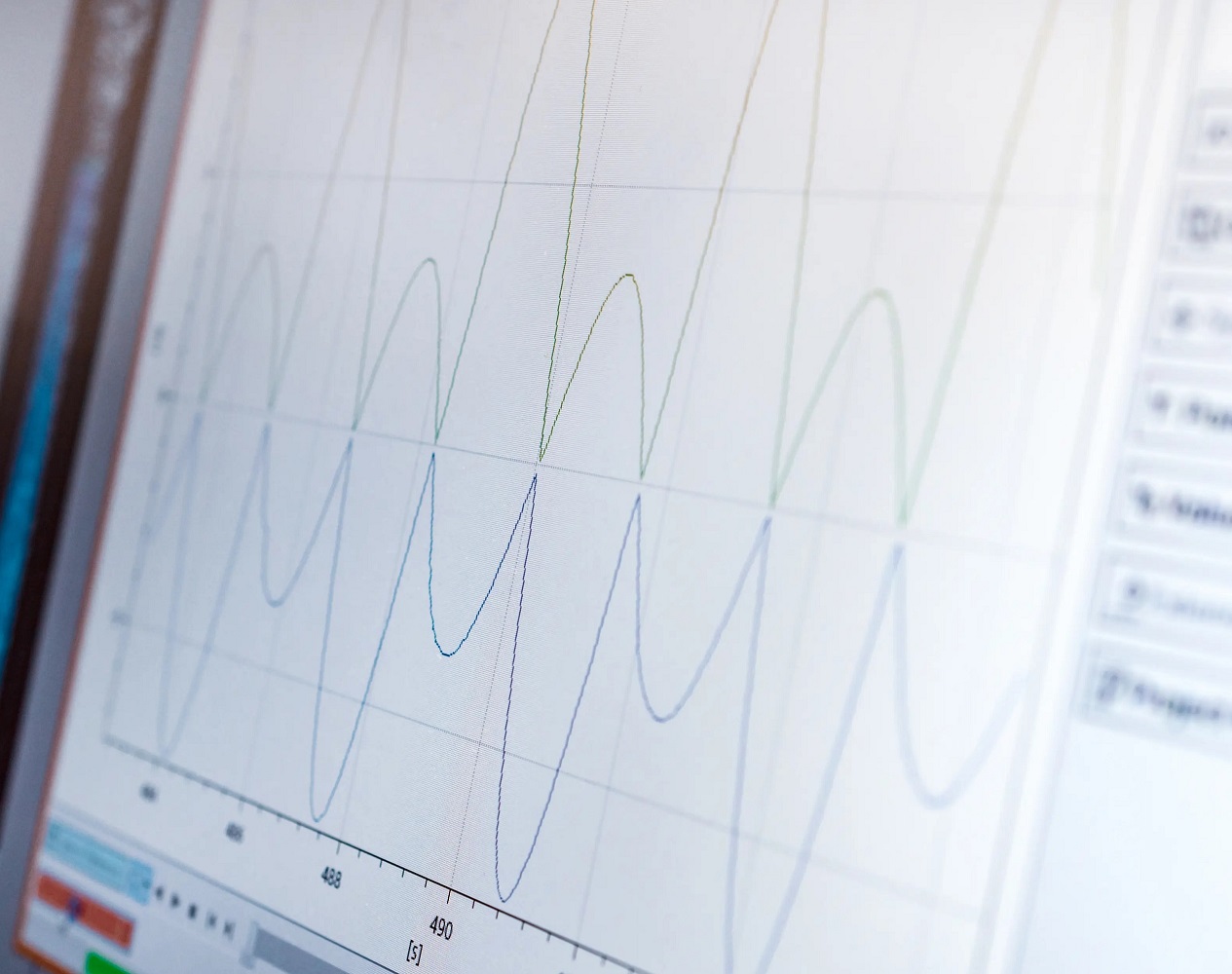
An impedance analyzer allows these quantities to be measured and graphically represented over a wide frequency range – often with several parameters simultaneously.
LCR meters: typical applications, advantages and limitations
Typical applications
- Fast sample measurements of resistors, capacitors and inductors.
- Incoming goods inspections with pass/fail decision at a defined inspection frequency.
- Simple production tests, focusing primarily on nominal value and tolerance.
Advantages
- Easy to use.
- Rapid single measurement of L, C or R.
- Cost-effective for standard tasks.
borders
- Usually only a few fixed frequencies.
- Often no extensive frequency sweeps or multi-parameter scans.
- Complex components (e.g., transformers, magnetic materials, printed circuit boards) can only be characterized to a limited extent.
- DC bias functions are limited or missing.
Impedance analyzer: Sweeps, resonances, multi-parameter analysis and bias
The Techmize TH2851 series is a precision impedance analyzer with test frequencies from 10 Hz to 130 MHz, a basic accuracy of 0.08%, four-pin auto-balance bridge technology, AC signals from 5 mV to 2 V and DC bias up to ±40 V / ±100 mA. It offers three measurement modes (spot, list, and graph scan), a 1601-point multi-parameter list function, and four-channel curve display with 16 split-screen layouts.
With test speeds up to 5 ms and SCPI compatibility (including Keysight E4990A/E4980A and HP4284A), the series is suitable for both laboratory tasks and automated testing systems.
Typical applications of the TH2851 series
- Passive components: Analysis of capacitors, inductors, magnetic cores, resistors, piezoelectric components, transformers, chip and network components.
- Semiconductor devices: parasitic parameters of integrated LED driver circuits, C-VDC properties of varactors, parasitic parameters of transistors and integrated circuits.
- Other components: Impedance evaluation of printed circuit boards, relays, switches, cables, batteries.
- Dielectric materials: Dielectric constant and loss angle of plastics, ceramics and other materials.
- Magnetic materials: Permeability and loss angle of ferrites, amorphous and other magnetic materials.
- Semiconductor materials and liquid crystal cells: dielectric constant, conductivity, C-V and elasticity properties.
VNA: typical RF and network applications
A VNA specializes in the analysis of RF networks. Typical tasks include:
- Characterization of filters, matching networks and antennas.
- Measurement of reflections and transfer factors (S-parameters).
- Optimization of the matching between source, line and load.
While the impedance analyzer focuses on the component and material properties, the VNA primarily considers signal propagation in line and network structures.
Comparison table: LCR meter, impedance analyzer, VNA
| criterion | LCR meter | Impedance Analyzer (TH2851 Series) | VNA |
|---|---|---|---|
| Typical task | Single measurement of L, C, R | Detailed impedance and material analysis | Analysis of RF networks |
| Frequency coverage | Few fixed frequencies | 10 Hz to 15–130 MHz, depending on the model | RF up to the GHz range |
| Measured variables | L, C, R | Impedance, losses, material parameters, C-V properties | S-parameter, reflection, transmission |
| Sweeps / Scans | Rather limited | Point, list, and graphic scan, 1601-point lists | Frequency sweeps for networks |
| Bias functions | Limited, depending on the device | AC signal 5 mV-2 V, DC bias up to ±40 V / ±100 mA | RF power and bias options |
| Typical deployment locations | Simple quality control, goods receipt | Laboratory, quality assurance, automated production | RF development, RF systems |
CTA: If you are unsure whether an LCR meter, an impedance analyzer, or a VNA is suitable for your task, let us review your measurement task: Have your measurement task reviewed free of charge .
Selection by application
Capacitors
Besides capacitance and tolerance, ESR, loss factor, and frequency response are crucial. An impedance analyzer like the TH2851 series displays these effects across the relevant frequency range.
Inductors and ferrites
Inductors and magnetic cores require consideration of inductance, losses, saturation, and frequency-dependent permeability. The TH2851 series explicitly supports the evaluation of magnetic materials.
transformers
For transformers, leakage inductance, losses, and resonances are among the relevant parameters. These characteristics can be determined using frequency sweeps across various operating ranges.
semiconductor
Parasitic capacitances and C-V characteristics play a significant role in LED drivers, varactors, transistors, and ICs. The TH2851 series addresses these challenges with DC bias and suitable measurement modes.
Circuit boards and cables
Printed circuit boards, relays, switches, cables and batteries can be evaluated with regard to their impedance and possible sources of interference – helpful, for example, for EMC-related issues and power integrity analyses.
Material characterization
Plastics, ceramics, semiconductor materials and liquid crystal cells can be characterized with respect to dielectric constant, loss angle, conductivity and C-V properties.
Production inspection
Sorting functions and graphical analysis tools of the TH2851 series support automated component testing and quality control in laboratory and manufacturing.
Classification of the TH2851 series and model selection
The TH2851 series comprises five models with identical basic accuracy of 0.08% and AC signal ranges from 5 mV to 2 V and DC bias up to ±40 V / ±100 mA. The main difference is the maximum test frequency:
- TH2851-015: 10 Hz–15 MHz
- TH2851-030: 10 Hz–30 MHz
- TH2851-050: 10 Hz–50 MHz
- TH2851-080: 10 Hz–80 MHz
- TH2851-130: 10 Hz–130 MHz
For tasks in the lower MHz range, 15 or 30 MHz is often sufficient. Applications with relevant effects in the higher double-digit MHz range benefit from 80 or 130 MHz.
Details about the models can be found on the product page: View TH2851 models and technical specifications .
Common mistakes when choosing a device
- Incorrect frequency range – relevant effects lie above the maximum test frequency.
- No or unsuitable DC bias – the component is not measured under realistic conditions.
- Too few parameters are considered – only L or C, but not ESR, loss factor or parasitic components.
- No automation – sorting functions and SCPI connectivity are considered too late.
- Inappropriate contact – measurement errors due to incorrect geometry dominate the result.
Conclusion
LCR meters remain the first choice for simple, point-based measurement tasks. However, as soon as frequency response, parasitic effects, and material properties are the focus, an impedance analyzer like the Techmize TH2851 series is the appropriate solution. VNAs complement the picture in high-frequency engineering when networks and transmission links are being investigated.
The TH2851 series combines a wide frequency range from 10 Hz to 130 MHz with multi-parameter scans, DC/AC bias, sorting functions and SCPI integration – making it suitable for development engineers, testing laboratories, quality assurance, production as well as universities and research institutions.
FAQ
What is the TH2851 series particularly suitable for?
For the precise characterization of passive components, semiconductor components, printed circuit boards, cables, batteries, and dielectric, magnetic, and semiconducting materials in the range of 10 Hz to 130 MHz.
Can I use the TH2851 series to measure materials as well as components?
Yes, the series supports the determination of dielectric constant, loss angle, permeability, conductivity and C-V properties of various materials including liquid crystal cells.
What role does DC bias play?
With DC bias up to ±40 V and ±100 mA, components and materials can be measured under realistic operating conditions, such as varactors, LED drivers or dielectric materials under bias.
How fast does the TH2851 series measure?
The maximum test speed is up to 5 ms per measurement, making it suitable for automated sorting and testing applications.
How can the TH2851 series be integrated into existing test systems?
The supported SCPI command set and compatibility with established devices allow the series to be integrated into existing control and evaluation software.
What models are available in the TH2851 series?
Five models are available: TH2851-015, -030, -050, -080 and -130 with maximum test frequencies of 15, 30, 50, 80 and 130 MHz respectively.
Final CTA:Have your measurement task reviewed without obligation – send us your measurement task and receive a well-founded assessment of whether and which TH2851 model is suitable for your application.