

CAN loggers store messages with timestamps. This guide explains Classical CAN and CAN FD, signal decoding, and the data path for remote diagnostics – with suitable CANedge loggers for SD card, WLAN, and LTE.
At a glance
- A CAN log contains messages and timestamps; understandable measured values only arise through appropriate decoding.
- CAN FD offers up to 64 bytes of user data and optionally a faster data phase.
- The CANedge models support Classical CAN and CAN FD; their data path differs via SD card, WLAN or LTE.
What a CAN logger actually records
A CAN logger records messages from a vehicle or machine bus: specifically, the identifier (CAN ID), user data, and timestamps. This allows you to trace which data was present on the connected bus at any given time. However, the file does not automatically provide plain text such as engine speed, temperature, or battery status. For that, the meaning and encoding of the signals must be known.
A measurement therefore begins with a specific question: Is the goal to isolate a sporadic error, compare an operating state, or document a longer field test? Bus access, recording duration, and the selection of relevant messages are determined by this question. For later analysis, the raw data, measurement configuration, and the signal description used should all remain traceable.
Classical CAN and CAN FD: Differences and Compatibility
The CAN data link layer, including CAN FD, is standardized in ISO 11898-1. CAN FD increases the amount of payload per frame from a maximum of 8 to 64 bytes. BRS stands for "Bit Rate Switch": When the switching is enabled, the data phase can use a higher bit rate than the arbitration phase, in which bus access is negotiated.
The achievable data bitrate depends on factors such as transceivers, line topology, and operating conditions. Therefore, a general upper limit of 8 Mbit/s does not represent a universally valid CAN FD limit.
CAN FD controllers can also process Classical CAN frames. Classical controllers, on the other hand, do not understand FD frames and can react to them with error frames. A mixed network therefore requires a specifically appropriate communication strategy.
| feature | Classical CAN | CAN FD |
|---|---|---|
| Usage data per frame | Up to 8 bytes | Up to 64 bytes |
| Bitrate | A nominal bitrate, up to 1 Mbit/s | Nominal bitrate; with BRS separate data bitrate |
| CAN identifier | 11 or 29 bits | 11 or 29 bits |
| Controller | Understands Classical CAN frames | Supports Classical CAN and FD frames |
Raw data becomes signals: DBC and other descriptions
A DBC file is a common CAN database in text format. It describes, for example, which bits of a message belong to a signal, the byte order, and how scaling, offset, and unit are to be applied. Only with this information does a raw value become an interpretable measurement.
DBC is a practical exchange format for this purpose, but not a mandatory requirement: The same rules can also originate from another documented signal specification and be implemented in suitable software. The crucial point is that the description matches the specific vehicle, control unit, and software version. Without this information, any CAN data stream cannot be reliably decoded based solely on its identifiers.
Local recording with the CANedge1
The CANedge1 from CSS Electronics supports both Classical CAN and CAN FD. It stores the data on an SD card in MDF4 format (.MF4). This makes it suitable for measurements where the data is subsequently extracted on-site – on the test bench as well as during vehicle testing.
The selection process is therefore less about whether the device is "stationary or mobile" than about whether automatic remote transfer is required. Before extended use, a short test recording is recommended: Are the bus parameters and timestamps correct, are the required messages included, and can the intended analysis software process the file?
Remote diagnostics: from the vehicle via WLAN to the evaluation
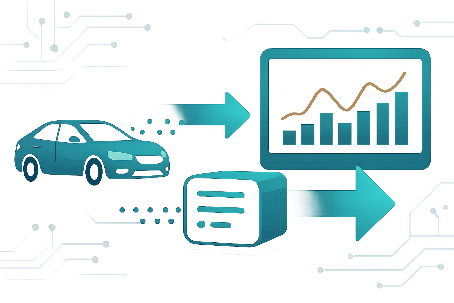
Remote analysis requires not only CAN access but also a data path to the analysis location. CAN FD provides neither an internet connection nor its own diagnostic service. UDS is also a separate protocol layer: passively recording existing messages is different from actively querying a control unit with diagnostic services.
The CANedge2 complements local recording with Wi-Fi. It can automatically transfer completed log files to a configured S3-compatible server, for example, as soon as the vehicle connects to an available Wi-Fi network. This is file-based data transfer and not an automatic continuous real-time stream. Wi-Fi access, server access, and subsequent processing must be configured and tested with a real test file.
Mobile data collection with LTE and CANedge3
If data transfer is required outside of an available Wi-Fi network, the CANedge3 offers a mobile data connection. The version linked here combines LTE with GNSS and IMU. This allows recorded bus data to be analyzed along with position and motion information. A suitable SIM card and adequate network coverage are required for mobile operation.
The most suitable solution depends on the measurement procedure: SD card for later data extraction, Wi-Fi for transmission via known access points, or LTE for mobile data transmission. However, remote access to log files does not replace a professional diagnosis. Meaningful results require appropriate signals, correct decoding, and an observation period suitable for the specific question being addressed.
Frequently Asked Questions
Can a classic CAN controller receive CAN FD messages?
No. CAN FD controllers also support Classical CAN; conversely, classic controllers do not understand FD frames and can trigger error frames. Sharing a bus must be planned accordingly.
Do I absolutely need a DBC file for CAN analysis?
No. Correct signal decoding rules are needed. DBC is a common format for this; another documented signal specification can also serve as a basis.
Is CAN FD already a solution for remote diagnostics?
No. Data acquisition, a transmission path, and evaluation are also required. Active diagnostic services like UDS are separate from this and require appropriate support from the control unit and the diagnostic tool.
Sources and further information
- CiA: CAN FD – the basic idea
- CiA: CAN data link layer generations
- CSS Electronics: CAN FD explained – bit rates and compatibility
- CSS Electronics: DBC files and signal decoding
- CSS Electronics: CAN Hardware Comparison
- CSS Electronics: CANedge1 – CAN data logger with SD card
- CSS Electronics: CANedge2 – CAN data logger with WLAN
- CSS Electronics: CANedge3 – LTE and GPS/IMU
- CSS Electronics: CANedge2 – Data transmission
- CSS Electronics: UDS diagnostic services