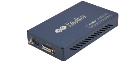
Description
eMMC and SD Electrical Validation and Protocol Decode Software offers electrical measurements compliance testing and protocol decoding as specified in eMMC and SD specifications.PGY-MMC-SD-SDIO Electrical validation and Protocol decode software run in Tektronix Oscilloscope provides electrical measurements and protocol decode at the click of a button. This allows engineers quickly check for eMMC and SD compliance and flexibility to debug the failure. In addition to this engineers can decode the command and response of eMMC and SD to debug the communication. PGY-eMMC and SD take advantage of digital channels of MSO and provide the decoding of eMMC and SD data lines.
Features MMC/SD/SDIO/eMMC Electrical Validation & Protocol Decode Software
- eMMC and SD (UHS-I) electrical measurements and Protocol testing software conforms to eMMC version 4.51 and 5.0 and SD version 3.01 specification.
- eMMC/SD/SDIO Protocol Aware Trigger features
- Industry first Protocol decoding CMD and Data (1 bit/4 bit and 8-bit mode) using MSO capabilities of Oscilloscope
- Supports SDR and DDR and Boot mode for electrical measurement and protocol Decode
- Fast frame capability allows protocol analysis of CMD in 100s of second time
- Software automatically identifies the read and write operations using CMD and apply the electrical parameter limits accordingly.
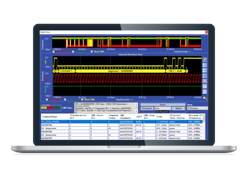
- Detail View provides efficient debugging capability by correlating the analog waveform, protocol messages and electrical measurements for each protocol packet in single view
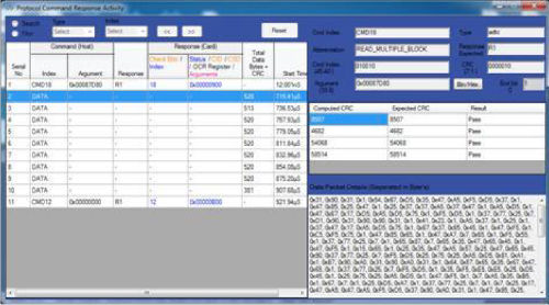
- Protocol View lists the protocol activities in sequential form to assist designers to know the host and card transactions
- Time stamp at the end of command token and time stamp at beginning of the response token in Protocol View enables designer to comply with specification and locate any anomaly in timing between host and card.
- Software displays the details of command and response in Protocol View and list the errors messages in card status for quick analysis
- Ability to store the eMMC and SD protocol data in CSV and txt format
- Utility features like zoom, undo, and fit to screen for easy manoeuvring the waveforms while debugging the cause to problem in Detail View makes it easy to use tool Software seamlessly integrates with Tektronix windows-based oscilloscope and supports live signal analysis using live channels of Oscilloscope
- Supports data analysis for long record length and more acquisition memory of oscilloscope enables analysis of protocol events for longer duration
- Report generation in pdf format.
- Supports wfm and isf file formats of Tektronix oscilloscope for offline analysis
Applications
- Protocol Analysis
- eMMC and SD (UHS-I) Electrical Compliance Test (Supports eMMC4.42, 4.51 and 5.0 & SD3.01)
- Correlation of Analog waveform, Protocol activities and Electrical Measurements
Seamless Integration with Oscilloscope
PGY- MMC and SD Electrical Validation and Protocol Decode Software runs inside the Tektronix high performance windows oscilloscopes. Automatically imports the data from oscilloscopes live channels. Also supports Tektronix. wfm and .isf file formats. This enable live and offline testing of eMMC and SD Signals.

- Provides the flexibility to select type of Card interface to be tested and related Bus speed modes
- Flexibility select necessary or all electrical measurements
- Save and recall of application setup for repetitive testing at different times
- Supports single and continuous test mode using oscilloscope live data
- Online help
eMMC/SD/SDIO Protocol Aware Triggering
For efficient test and debugging eMMC/SD/SDIO, it is important to capture signals at right condition. PGY- MMCSD software provides protocol aware triggering along serial pattern trigger option of the oscilloscope to capture signals at specific event in CMD line.
- Flexibility to trigger on command or response
- Offers all the standard triggers patterns with command and Response
- Flexibility to edit trigger pattern

Automated Electrical Validation & Protocol Software
As per the specification of eMMC and SD, the measurement limits are different for read and write operation. The PGY-MMC-SD measurement algorithms automatically find the read and write operations and validates with the respective limits. This enables you to save time in identifying the read and write operation and isolating any compliance issues.

- Lists electrical measurements with mean, minimum and maximum values measured for the entire acquired waveform
- Indicates if measurement exceeds the min or max limits by orange color
- Lower and Upper limits of the electrical measurements are compared against measured values
- Supports Electrical Measurements as per eMMC 4.41 and 4.51 and UHS3.1 Specification.
- Automated identification read and write operation and apply electrical limits as per eMMC and UHS-I specification
Timing Parameters between CMD, Response and Data
EMMC specifies the minimum and maximum cycles to present between the host and device to ensure interoperability. PGY-MMC-SD analyzes the data for these specifications and offers results.

Protocol View
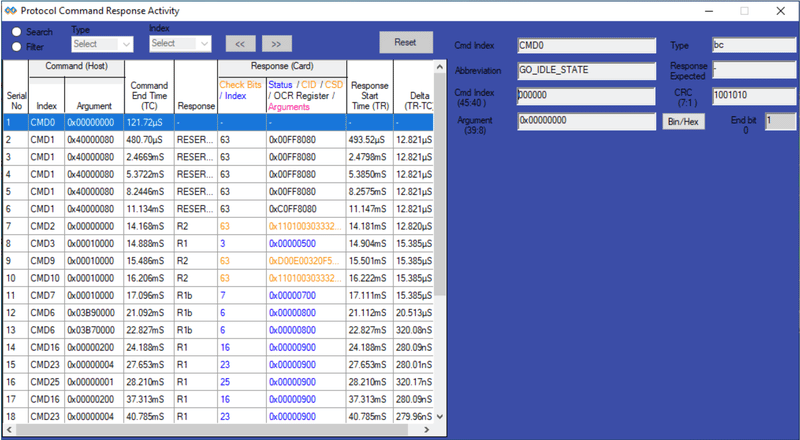
The PGY-MMC-SD-SDIO software lists all the protocol activity between the host and card. Engineers can now quickly view the command and its corresponding response from card. Selected protocol activity details are listed on right side of the list table. Now Engineers can know the errors reported by card or any other message to host without struggling to know the content of each message.
Characterization of PHY layer by custom limit setup
The PGY-MMC-SD-SDIO is not just for standard electrical compliance testing, you can also vary the limits and test your device with custom limits. The intuitive limits and reference level setup allow you to configure the limits and reference levels for your custom testing needs. This enables you to test your device beyond the specification and characterize it.

Powerful Debug environment: Detail view
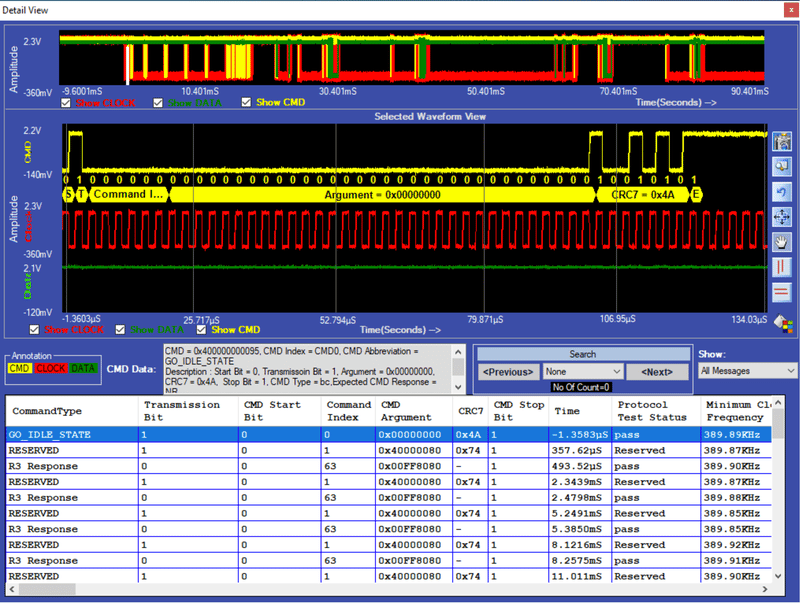
In Detail View, engineers can view the analog waveform, details of protocol and electrical measurements in single view. If there is any failure in electrical measurement or error in protocol messages, designers can quickly correlate the protocol data with analog waveforms. These protocol errors can be caused due to the failure in electrical measurements. User can select any row in the detail view; corresponding analog waveform will be zoomed and displayed. In the same row, engineers can view all the electrical measurements corresponding to the selected row. Utility features such as zoom, cursors, and markers make custom measurement while debugging.
Detail view provides following capabilities:
- Plots the acquired waveform in waveform view window
- Lists all decoded command and response tokens in each row in decode table
- Indentifies of type of command and response for easy protocol interpretation
- Lists respective electrical measurements for command and response for each row
- Selected Protocol command or response’s related analog waveform is plotted in a window.
- Bus Diagram view overlays protocol data for the selected row along with waveform
- Snap button enables storing selected waveform window for report generation purpose
- Zoom, fit to screen, pan, undo, vertical and horizontal cursors enables quick analysis and measurement of electrical signals
Industry First Decoding of CMD and data Signals:
PGY-MMC-SD-SDIO everages powerful capabilities of Digital Channels of MSO70000/5000 series oscilloscope to provide industry decoding of data signals in eMMC and UHS-I.
Protocol test
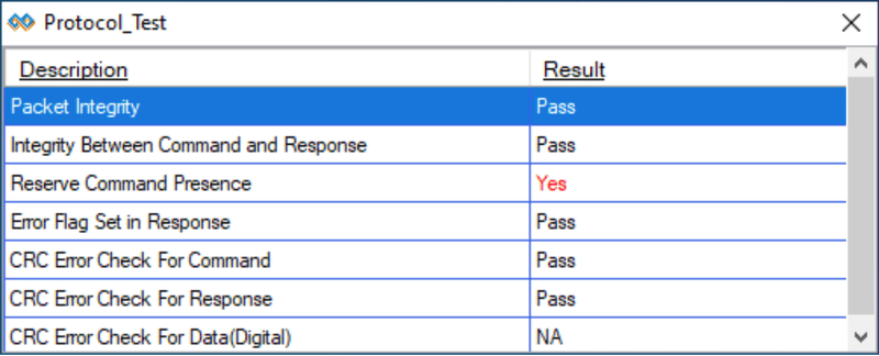
PGY-MMC-SD software automatically checks for Protocol Integrity. This allows very easy method ensuring protocol packets are as per protocol specifications of eMMC, UHS-I Specifications.
Supported Tektronix Oscilloscopes
- DPO 5000
- MSO 5000
- DPO 7000
- DPO/MSO/DSA 70000
- MSO5
- MSO6
With a bandwidth of 500MHz and more and standard RL






.jpg)
.jpg)
.jpg)
.jpg)

