Description
ONFI Electrical Timing Analysis Software offers electrical measurements compliance testing as specified in ONFI specifications. PGY-ONFI Electrical Timing Analysis software runs in Tektronix Oscilloscope and provides electrical measurements at the click of a button. It allows a quick check for ONFI compliance and flexibility to debug the failure. In addition, engineers can decode the command and response of ONFI and debug the communication. PGY-ONFI takes advantage of the digital channels of MSO and decodes ONFI data lines.
Features ONFI Protokoll Software
- Provides electrical measurement software which conforms to Open NAND Flash Interface Specification Revision 4.0
- Supports SDR, NVDDR, NVDDR2, and NVDDR3 interfaces for electrical timing measurements
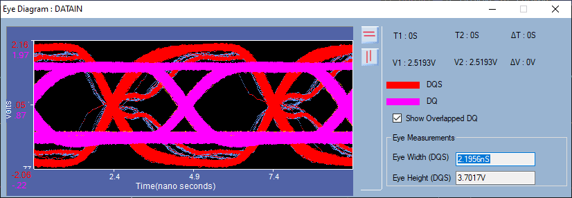
- Eye diagram for DQ and DQS helps in quickly identifying signal integrity problems
- Provides worst-case measurements results over a number of acquisitions
- Provides flexibility to link the worst timing measurement to waveform from single or multiple acquisitions of signal
- Provides the cumulative hits of each measurement over multiple acquisitions
- The software automatically identifies the Command, Address, Data Input, and Data Output cycles in ONFI traffic
- Automatically applies measurement limits based on model selection
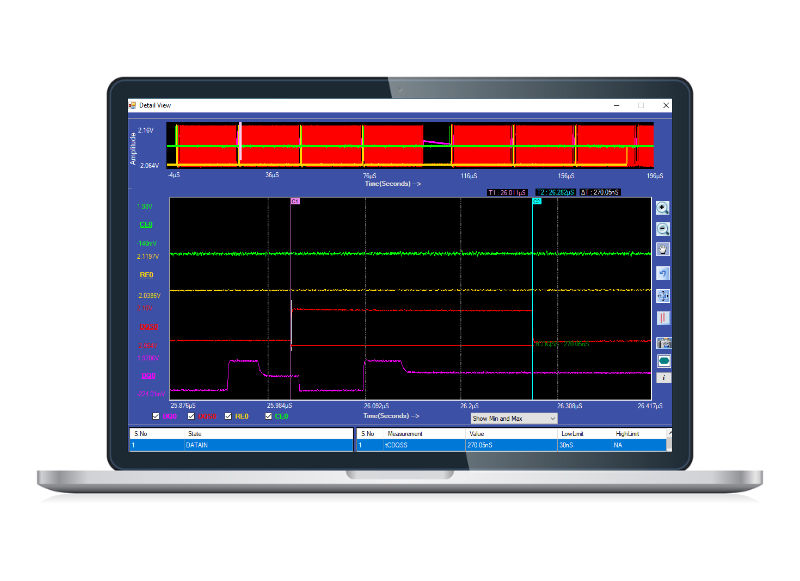
- Detail View provides efficient debugging capability by correlating the analog waveform and electrical measurements for Command, Address, Data Input, and Data Output cycleS
- Annotating electrical measurements on waveform for easy debug
- Ability to export the CVS and txt data to a CSV file
- Report generation in pdf format
Seamless Integration with Oscilloscope

PGY- ONFI Electrical Timing Analysis Software runs inside the Tektronix high performance windows oscilloscopes. The application automatically imports the data from the oscilloscope live channels. The application supports .wfm file format of Tektronix for offline analysis. This enable's live and offline testing of ONFI Signals.
- Based on the ONFI signals being probed using the four live analog channels, software will automatically enable the possible timing measurements for these signals
- Forty five automated timing measurements as per ONFI standard apart from few general measurements such as frequency, duty cycle
- Save and recall of application setup for repetitive testing at different times
- Supports single and continuous test mode using oscilloscope live data
- On-line help
Automated Electrical Timing Measurements
As per the specification of PGY-ONFI, the measurement limits are different for each interface and each mode. The PGY-ONFI measurement algorithms automatically find the mode and validates with the respective limits. This enables the customer in identifying the various modes and isolating any compliance issues.
- Lists electrical measurements with mean, minimum and maximum values measured for the entire acquired waveform
- Indicates if the measurement exceeds the min or max limits by orange color
- Save and recall of application setup for repetitive testing at different times
- Supports single and continuous test mode using oscilloscope live data
- On-line help
- ower and Upper limits of the electrical measurements are compared against measured values
- Supports Electrical Measurements as per ONFI 4.0 Specification.

Powerful Debug environment: Detail view
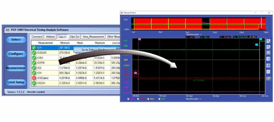
PGY-ONFI Software provides two types of debugging capabilities. In one of them, the worst-case result can be selected and linked directly to the waveform as shown here. Software provides the flexibility to define the number of acquisitions and the results will include worst case results for all these acquisitions. Software can link the worst-case results to corresponding waveform acquisition using simple right click of mouse.
In Detail view debug mode, PGY-ONFI software will display the waveform plot of last acquisition and all electrical timing measurements for that acquisition. Software has the flexibility to display only failed, min and max and all timing measurement results that are available for the acquired waveform. Linking any of the measured results to waveform helps in debugging the results.
Eye-Diagram
PGY-ONFI provides the eye-diagram feature for easy correlation of DQS and DQ timing relationship. This enables quick view of any BER during the data-in or data-out operation. It also provides overall view of the total jitter present in DQ and DQS.
- Plots the acquired waveform in the waveform view window
- Lists respective electrical measurements for command, address, data input, and data output cycles
- Option to select only the min/max or failed measurements from the complete list of measurements
- Zoom, fit to screen, pan, undo, vertical and horizontal cursors enables quick analysis and measurement of electrical signals
Supported Tektronix oscilloscopes
- DPO 70000
- MSO 70000
- DSA 70000
